Full wave bridge rectifier operation Full wave bridge rectifier – circuit diagram and working principle Rectifier circuit diagram
GK, Current Affairs, Tutorials & Articles: Rectifiers Theory with
Rectifier wave bridge operation half working animation current input cycle forward during gif diodes tutorial reverse biased positive d3 d1 What should i consider when choosing the right diode… Rectifier wave tap centre waveform circuit diagram working
Full wave bridge rectifier
Rectifier circuit bridge diagram wave working detailsFull wave bridge rectifier circuit diagram Engineering photos,videos and articels (engineering search engineSi lab.
Full wave bridge rectifier – circuit diagram and working principleFull wave bridge rectifier – circuit diagram and working principle Centre tap full wave rectifier circuit operation,working,diagram,waveformGk, current affairs, tutorials & articles: rectifiers theory with.

Draw a circuit diagram of a full wave rectifier. e toppr.com
Rectifier input waveforms diodes transformer explain topprBridge rectifier: functions, circuits and applications Phase control wave dc rectifiers power ac explained minutesFull wave bridge rectifier.
Bridge wave rectifier circuit output half diagram cycle principle working rectifiers input theory currentPhase control rectifiers explained in 2 minutes Rectifier principle understanding simplify lookedRectifier circuit diagram.

Rectifier bridge circuit half diagram phase rectification wave figure car engineering articels engine search videos extended shown idea
Full wave bridge rectifier circuit diagramRectifier wave bridge circuit diodes operation negative forward becomes figure below its biased Rectifier transformer waveform tapped etechnogRectifier bridge wave diagram schematic illustration circuits.
Rectifier bridge wave circuit diagram regulator icCircuit rectifier bridge wave rectifiers output input rectified properly dc ac voltage amplifier Rectifier wave bridge circuit diagram diode voltage peak operation fig inverse disadvantages advantages value itsRectifier bridge circuit application basics output diagram waveform applications circuits diodes used diode dc power voltage transformer resultant peak advantages.

Rectifier diode rectifiers circuits
Rectifier circuit diagram wave output waveform inputThree phase full wave rectifier working, diagram and output waveform General circuit diagram of the bridge rectifier (a) full wave bridgeRectifier bridge diagram circuit wave construction principle working.
Rectifier phase controlled wave waveform rectifiers outputRectifier output dc wave waveform bridge circuit diagram voltage principle working input positive converts Full wave bridge rectifier – circuit diagram and working principle.


GK, Current Affairs, Tutorials & Articles: Rectifiers Theory with
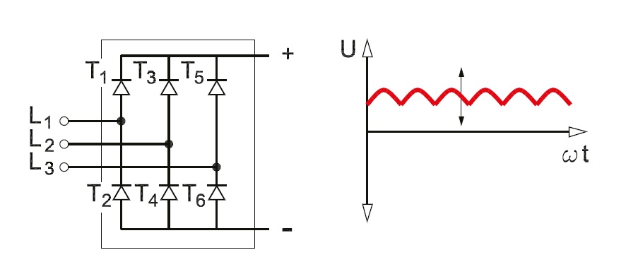
Three Phase Full Wave Rectifier Working, Diagram and output waveform

Rectifier Circuit Diagram | Half Wave, Full Wave, Bridge - ETechnoG
.jpg)
Phase Control Rectifiers Explained in 2 Minutes - Society of Robotics

What should I consider when choosing the right diode… | CircuitBread

Draw a circuit diagram of a full wave rectifier. E toppr.com

General circuit diagram of the Bridge rectifier (a) Full wave bridge

Full Wave Bridge Rectifier Operation - Inst Tools